
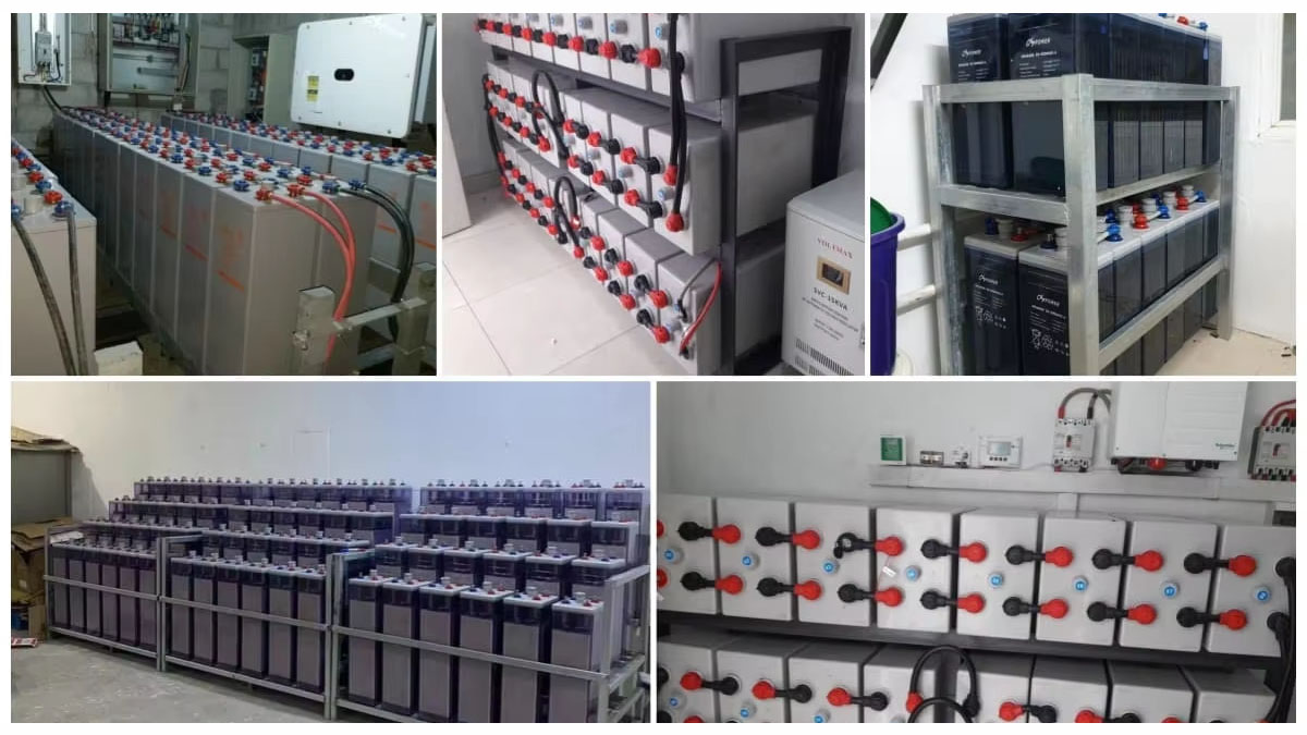
Reliable backup power is often judged only when the main supply disappears. In a factory, telecom facility, data center, substation or commercial building, that short period can be critical. Control systems may need to remain active, communication equipment must continue operating, and essential loads may need to stay online until utility power is restored or a generator takes over.
The battery bank is the energy source that makes this possible.
For larger stationary backup installations, 2V VRLA cells are commonly considered because individual cells can be assembled into battery banks designed around the DC voltage and autonomy required by the application.
Choosing the right configuration, however, involves much more than selecting a capacity in Ah. Load characteristics, discharge time, temperature, charging conditions, installation space, maintenance and lifecycle requirements all influence the final selection.
This guide explains the practical considerations for businesses evaluating 2V VRLA battery systems in India.
What Is a 2V VRLA Battery?
A 2V VRLA battery is a Valve Regulated Lead Acid cell with a nominal voltage of 2 volts.
Rather than using one large battery block, multiple cells can be connected in series to create the DC voltage required by a UPS or industrial power system.
For example:
2V cells → Series connection → Required DC voltage → UPS battery bank
VRLA construction is designed to operate as a regulated, low-maintenance stationary battery system. Depending on the product, the technology may use AGM or GEL construction.
The correct choice depends on the intended duty cycle, discharge characteristics and environmental conditions.
Why 2V Cells Are Used in Large Battery Banks
Large UPS and industrial DC systems often require battery banks with higher voltage and substantial capacity.
Using individual 2V cells provides flexibility when creating these configurations.
The arrangement can be designed around:
- Required DC voltage
- Battery capacity
- Backup duration
- Discharge current
- UPS specifications
- Available installation space
For large installations, individual cell monitoring can also make it easier to identify a weak cell within the battery string.
How a VRLA Battery Stores and Delivers Energy
The operating process is straightforward.
During normal utility operation, the charger maintains the battery at the appropriate charging condition.
When an interruption occurs, stored chemical energy is converted into electrical energy and supplied to the connected system.
The basic cycle is:
Normal supply → Charging → Energy stored → Power interruption → Battery discharge → Supply restored → Recharge
The actual charging and discharge characteristics depend on the battery model and manufacturer’s specifications.
Main Components of a 2V VRLA Cell
A stationary cell contains several important components.
Positive and Negative Plates
These plates participate in the electrochemical reaction responsible for storing and releasing energy.
Separators
Separators keep the plates apart while allowing the required electrochemical process to take place.
Electrolyte
The electrolyte enables the chemical reaction between the plates. Its physical form depends on whether the cell uses AGM or GEL construction.
Container
The container provides mechanical protection for the internal components.
Pressure Relief Valve
The regulated valve helps manage internal pressure during operation.
Together, these components allow the cell to provide controlled energy storage for stationary applications.
AGM vs GEL VRLA
Not every VRLA battery is identical.
AGM
Absorbent Glass Mat technology holds the electrolyte within a glass-mat separator.
It is commonly considered for:
- UPS systems
- Telecom backup
- IT infrastructure
- Commercial power systems
- Industrial standby applications
GEL
GEL technology uses a gelled electrolyte and may be considered for applications requiring particular cycling or environmental characteristics.
The selection should be based on:
Load + Runtime + Charging + Temperature + Duty Cycle
Rather than choosing between AGM and GEL purely on general advantages, the actual manufacturer’s discharge and charging specifications should be reviewed.
Standby Operation vs Frequent Cycling
This is one of the most important points when selecting a battery.
Standby Application
The battery remains charged under normal conditions and is mainly discharged when utility power fails.
This is common in UPS installations.
Cycling Application
The battery is regularly charged and discharged during normal operation.
Some renewable-energy and energy-storage applications operate this way.
A battery designed primarily for standby service should not automatically be selected for an application involving frequent deep cycling.
The expected operating pattern should be established before procurement.
Battery Capacity Is More Than an Ah Number
A common mistake is to compare batteries only by their ampere-hour rating.
The actual usable capacity depends on the discharge conditions.
Important factors include:
- Discharge current
- Required runtime
- End-of-discharge voltage
- Temperature
- Battery age
- System efficiency
For this reason, technical sizing should use the manufacturer’s discharge tables rather than relying only on the nominal capacity printed on the battery.
How to Estimate Battery Runtime
An initial calculation can start with:
Required Energy ≈ Load × Backup Time
However, practical battery sizing also needs to account for:
- UPS efficiency
- DC voltage
- Battery discharge characteristics
- Temperature
- Design margin
- Battery ageing
For critical applications, the final capacity should be verified against the manufacturer’s discharge curves.
Understanding C-Rate
Battery discharge is sometimes described using C-rate or a specified discharge duration.
A battery supplying a load over a short period can behave differently from the same battery discharged over a much longer period.
Therefore, a buyer should ask:
At what discharge duration is the rated capacity specified?
This is particularly important when comparing products from different manufacturers.
End-of-Discharge Voltage
A battery is not normally discharged until its voltage reaches zero.
The UPS or DC system operates with a defined end-of-discharge voltage.
This value affects how much usable energy can be obtained from the battery during the required backup period.
When requesting a battery quotation, provide the UPS manufacturer’s required discharge voltage whenever available.
Battery Bank Configuration
Multiple 2V cells are connected to create the required system voltage.
For example:
24 cells × 2V = 48V
60 cells × 2V = 120V
120 cells × 2V = 240V
These are simple examples rather than universal UPS configurations.
The actual number of cells should always be determined from the UPS or DC system design.
If greater capacity is required, multiple strings may be connected in parallel where permitted by the system design.
Battery Charging Requirements
The charging system is just as important as the battery itself.
The charger should be compatible with:
- Battery technology
- Number of cells
- DC voltage
- Charging voltage
- Charging current
- Temperature conditions
For standby installations, controlled float charging is commonly used.
The manufacturer’s charging specifications should always take priority over generic charging assumptions.
Recharge After a Power Failure
Battery performance also includes how quickly the system can recover after an outage.
Recharge time depends on:
- Depth of discharge
- Battery capacity
- Charger output
- Battery condition
- Required recovery period
This matters particularly for facilities that experience multiple power interruptions in a short period.
A battery that provides sufficient first-outage runtime may still be unsuitable if the charger cannot restore its energy within the required operating window.
Temperature and Battery Life
Temperature is one of the major factors affecting lead-acid battery ageing.
High temperatures can accelerate deterioration, while unsuitable low-temperature conditions can affect available capacity.
Before installation, consider:
- Ambient temperature
- Seasonal changes
- Ventilation
- Heat from nearby equipment
- Battery-room conditions
- Cabinet temperature
The manufacturer’s specified operating range should be used when designing the installation.
Installation Requirements
The battery bank should be treated as part of the electrical infrastructure rather than simply a collection of batteries.
Installation planning may include:
- Battery rack or cabinet
- Cable sizing
- DC protection
- Polarity
- Terminal connections
- Ventilation
- Floor loading
- Maintenance access
- Temperature control
Poor installation practices can reduce reliability even when the selected battery itself is technically suitable.
Battery Rack or Cabinet?
Both arrangements can be used depending on the application.
Rack Installation
A rack can provide convenient access to individual cells and is often considered for larger stationary battery banks.
Cabinet Installation
A cabinet provides an enclosed arrangement and can be useful where the site layout or equipment configuration calls for protected housing.
The choice depends on:
- Battery quantity
- Cell dimensions
- Available space
- Maintenance requirements
- Site conditions
- Project design
Battery Safety
Battery systems require appropriate electrical and maintenance procedures.
Important areas include:
- Correct polarity
- Short-circuit protection
- DC isolation
- Proper cable sizing
- Secure connections
- Safe handling
- Suitable PPE
- Ventilation where required
Installation and maintenance should be carried out according to the manufacturer’s instructions and applicable site requirements.
Battery Monitoring
A battery bank can appear normal while individual cells are beginning to deteriorate.
Monitoring can provide additional information such as:
- Individual cell voltage
- String voltage
- Temperature
- Charging condition
- Alarm status
- Internal resistance
- Battery health indicators
For mission-critical installations, this information can help maintenance teams identify abnormal behaviour earlier.
Battery Testing
Testing provides a better picture of battery condition than visual inspection alone.
Depending on the application, testing may include:
Voltage Testing
Checks the electrical condition of individual cells or strings.
Internal Resistance Testing
Can help identify changes in cell condition.
Capacity Testing
Provides information about the battery’s ability to deliver its required energy.
Discharge Testing
Can be used where actual backup performance needs to be verified.
The testing method and interval should be based on the battery manufacturer’s guidance and the criticality of the installation.
Common Reasons for Reduced Backup Time
If a UPS battery bank no longer provides its expected runtime, possible causes include:
- Battery ageing
- Increased connected load
- Incorrect sizing
- Poor charging conditions
- High operating temperature
- Weak cells
- Incorrect configuration
- Degraded connections
Troubleshooting should begin by comparing the present operating condition with the original system design.
Battery Ageing and Failure Indicators
A battery approaching the end of its useful service period may show:
- Reduced autonomy
- Repeated battery alarms
- Uneven cell voltages
- Increased internal resistance
- Physical deterioration
- Poor recharge performance
- Failed capacity tests
These indicators should be evaluated by qualified maintenance personnel before deciding whether individual cells or the complete bank needs replacement.
Battery Replacement
Replacement planning is particularly important for critical UPS systems.
Before replacing an existing bank, verify:
UPS model → DC voltage → Number of cells → Capacity → Discharge requirement → Physical dimensions → Charger compatibility
A replacement should not be selected solely because it has the same Ah rating as the old battery.
The new battery must be compatible with the complete system.
Battery Storage Before Installation
Batteries sometimes remain in storage before reaching the final project site.
Storage conditions can affect battery condition.
The supplier’s instructions should be followed regarding:
- Storage temperature
- Storage duration
- State of charge
- Recharge requirements
- Inspection before commissioning
For long-stored batteries, the condition should be verified before connecting them to the operational system.
Applications Across India
2V VRLA battery banks can be considered for a variety of stationary applications.
Manufacturing
Production control, automation and critical electrical systems.
Data Centers
Servers, storage, networking and IT infrastructure.
Telecom
Communication and network backup.
Substations
Protection, control and DC auxiliary systems.
Healthcare
Critical IT and selected medical-support infrastructure.
Commercial Buildings
Servers, security, communication and essential building systems.
Renewable Energy
Selected solar and hybrid applications where the operating profile suits the technology.
Railways
Selected signaling, communication and control applications.
Commercial vs Industrial Requirements
The battery selection process can differ depending on the environment.
| Factor | Commercial | Industrial |
|---|---|---|
| Typical loads | IT, communication, security | Automation, controls, industrial systems |
| Environment | Often controlled | Can be demanding |
| Runtime | Usually critical-load focused | Application dependent |
| Installation | Space may be limited | Dedicated areas may be available |
| Duty cycle | Often standby | Standby or cycling |
| Selection priority | Reliability and footprint | Reliability and operating conditions |
The classification alone should never determine the battery. The actual load and operating conditions are more important.
Integration With Online UPS
A typical UPS arrangement is:
Utility → Online UPS → Critical Load
with the battery connected to the UPS DC system.
During normal operation, the charger maintains the battery.
When utility power fails, stored DC energy is supplied to the inverter, allowing the UPS to continue powering the connected load.
The exact cell count and battery configuration depend on the UPS manufacturer’s DC bus requirements.
Integration With Diesel Generators
Many facilities combine:
Grid + UPS + Battery + DG Set
A typical sequence is:
Grid failure → Battery supports load → DG starts → UPS accepts generator supply → Battery recharges
This arrangement allows the battery to bridge the period between utility failure and generator availability.
Generator compatibility should be assessed during system design.
Solar and Hybrid Power Integration
A battery can also form part of a hybrid electrical system.
A project may combine:
Grid + Solar + Battery + UPS + DG
However, the suitability of VRLA technology depends on how often and how deeply the battery will be cycled.
Where frequent cycling is expected, other chemistries may need to be evaluated.
2V VRLA vs Lithium
| Factor | 2V VRLA | Lithium |
|---|---|---|
| Energy density | Lower | Higher |
| Physical footprint | Generally larger | Generally smaller |
| Standby applications | Established | Suitable |
| Frequent cycling | Application dependent | Often advantageous |
| Initial cost | Often lower | Often higher |
| Battery management | Conventional | BMS-based |
| Lifecycle considerations | Mature | Application dependent |
The right technology depends on the project’s operating profile rather than simply choosing the newer technology.
Total Cost of Ownership
Battery procurement should consider more than the initial quotation.
A useful evaluation includes:
Purchase + Installation + Maintenance + Charging losses + Replacement + End-of-life handling
For critical facilities, the financial impact of unexpected downtime should also be considered when comparing solutions.
Frequently Asked Questions
What is a 2V VRLA battery?
It is a 2-volt Valve Regulated Lead Acid cell designed for stationary backup and power-system applications.
Why are 2V cells used for large UPS systems?
They allow engineers to build battery banks around the required DC voltage and capacity.
Are AGM and GEL both VRLA technologies?
Yes. AGM and GEL are two different VRLA construction approaches.
Can these batteries be used with Online UPS systems?
Yes, when the battery-bank voltage, capacity, discharge characteristics and charging requirements match the UPS.
How many 2V cells are needed for a UPS?
It depends on the UPS DC bus voltage and the manufacturer’s specified battery configuration.
Can 2V cells be connected in parallel?
Multiple series strings may be connected in parallel where the system design permits it and appropriate engineering is followed.
How is battery runtime calculated?
Runtime depends on load, battery capacity, discharge characteristics, temperature, end voltage and system efficiency.
Is Ah the only factor when selecting a battery?
No. Discharge rate and manufacturer’s discharge data are equally important.
What is float operation?
It is a standby operating mode in which the battery remains connected to a charger and is maintained in a ready state.
Can VRLA batteries be used for frequent cycling?
Some models can support cycling, but the specific battery must be selected according to the expected duty cycle.
Does temperature affect battery life?
Yes. Operating temperature has a significant effect on lead-acid battery ageing and performance.
How should a battery bank be maintained?
Maintenance can include inspection, voltage checks, connection checks, temperature monitoring and periodic testing.
What causes reduced UPS backup time?
Battery ageing, increased load, poor charging, high temperature, weak cells and incorrect sizing can all contribute.
When should a battery bank be replaced?
Replacement should be considered when capacity declines, alarms increase, testing shows deterioration or the planned lifecycle is approaching its limit.
Can a 2V VRLA battery replace a 12V battery?
Not directly. The battery-bank design, voltage, capacity and physical arrangement must be evaluated.
Can VRLA batteries work with diesel generators?
Yes. They can be used as the battery component of a UPS system operating alongside a DG set.
Can VRLA batteries be used with solar?
Yes, for applications where the charging and cycling profile is appropriate.
How do I compare two battery brands?
Compare discharge curves, capacity, charging requirements, temperature range, dimensions, warranty and technical documentation rather than price alone.
What documents should a supplier provide?
Depending on the project, this can include datasheets, discharge information, installation instructions, testing documentation and warranty details.
Can Anushri Systech support industrial battery requirements?
Anushri Systech can evaluate battery requirements based on the customer’s UPS, load, autonomy and application information.
Conclusion
A dependable battery bank starts with correct engineering rather than simply selecting a high-capacity product.
For large UPS and stationary power applications, 2V VRLA cells provide a flexible way to build battery banks around specific DC voltage and backup requirements. Their suitability, however, depends on the operating profile, discharge conditions, temperature, charging system, installation and maintenance strategy.
For businesses in India and international buyers sourcing from India, the most effective procurement approach is to provide the actual system requirements first and then evaluate the battery technology, configuration and supplier accordingly.
The right battery is the one that matches the application, not simply the one with the highest Ah rating or lowest price.
Discuss Your Battery Requirement
If you are planning a new UPS installation, replacing an existing battery bank or preparing an industrial project, share your technical requirements with the Anushri Systech team.
Email: sales@anushri.info
Phone: +91 9841698180
Address: No. 2/27, Luz Avenue 3rd Street, Mylapore, Chennai – 600004, Tamil Nadu, India